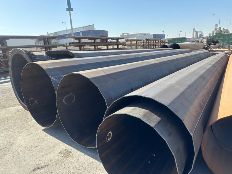
Tower Base & Leg Components
Drawing-defined angle-steel legs, base components and connection plates for lattice-tower assemblies.
Where these components fit
For lattice-tower fabrication or replacement scopes where the assembly drawing and piece marks define the required members. This is a component package, not a claim to supply an independently approved complete tower or building structure.
Project specification
Specification & configuration
Configuration choices
- Angle-steel tower legs and connecting members
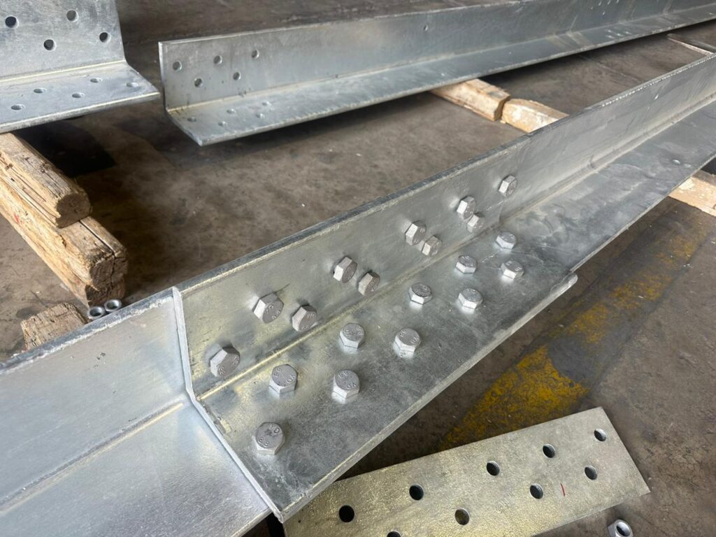
- Base-shoe assemblies, base plates and stiffener plates
- Nested or connection plates and their matching hole patterns
- Bolts and associated hardware when included in the agreed bill of materials
Material & surface treatment
The reference leg/base drawing identifies ST52 for the listed pieces. The precise standard and edition must be agreed for a new order; do not substitute Q-grade, S-grade or ASTM steel without the controlling specification.
Specify galvanizing or another coating system, coating standard and required inspection in the RFQ. The component photograph does not establish coating thickness or a certified finish.
Existing technical information
A historical tower-parts set contains assembly drawings, piece-mark drawings and bills of materials for legs, base components and plates. The selected dimensions below describe one reference assembly. Private drawings and commercial records are not public downloads.
Reference only: values below describe one historical leg/base assembly. They are not a stocked size range, an interchangeable grade claim or a structural design approval.
- Application
- Lattice-tower leg/base and connection assemblies defined by approved project drawings.
- Structure & geometry
- Angle members, base components and plates matched by piece mark and revision.
- Material & finish
- ST52 appears in the selected historical drawing. Current material specification and coating must be agreed.
- Design standard
- Drawing-led component scope; specify the material, fabrication and inspection standards in the RFQ.
- Supply boundary
- Tower legs/base components and associated plates; hardware only as agreed in the bill of materials.
- Documentation available
- Historical assembly, piece-mark and bill-of-material drawings; current revision and release conditions confirmed on request.
- Reference leg — angle section
- 250 × 250 × 35 mm
- Reference leg — piece length
- 996 mm
- Reference base plate — size
- 600 × 600 × 60 mm
- Reference drawing material
- ST52
What we need to confirm
- Assembly revision, piece marks, quantities and matching connection details
- Material specification, dimensional/hole tolerances and welding requirements
- Surface treatment, material traceability and inspection/documentation scope
No universal hole pattern, load capacity, tolerance or delivery time is assumed. Send the relevant drawing sheets or parts schedule for a configuration-specific enquiry.
Technical information
Prepare a complete technical brief
Need a dimension or a drawing?
Send the required configuration, revision and site conditions. We will confirm which drawings, material records and inspection documents apply to your enquiry.