Telecom Monopole Assembly
A drawing-led steel pole assembly for antenna support, with coordinated shafts, top framing, access and anchoring interfaces.
Where this assembly fits
For telecom projects that need a single-pole support and coordinated antenna, feeder and access arrangements. Confirm the antenna schedule, mounting elevations, site loads and foundation interface before selecting a configuration.
Project specification
Specification & configuration
Configuration choices
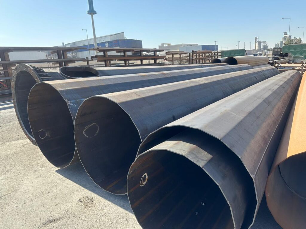
- Steel pole shaft and base connection
- Top camouflage framing and GRP cladding interfaces where required
- Internal access, cable outlets and antenna or feeder mounting arrangements
- Anchor assemblies and installation interfaces specified with the foundation design
These elements are scoped individually. They are not automatically included in every enquiry.
Material & surface treatment
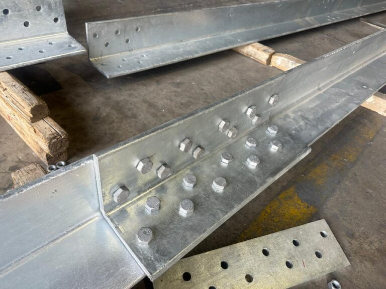
The historical pole schedules identify Q355B for the shaft and top framing, with hot-dip galvanizing specified for those assemblies. Agree the material standard, coating requirement and inspection documents for the current project; a historical designation does not establish material equivalence or certification.
Existing technical information
35 m and 40 m fabrication drawing sets and assembly schedules support this product scope. The reference dimensions shown here belong to the 35 m drawing; they must not be applied to the 40 m configuration. Original project drawings are available for a suitability discussion, subject to the applicable revision and confidentiality.
Reference only: the dimensions below are from a historical 35 m fabrication drawing. They are not a standard product range or an approved design for a new site.
- Application
- Telecom antenna and feeder support; mounting loads and site design basis required.
- Structure & geometry
- 35 m and 40 m assemblies are represented in historical records; other heights require project review.
- Material & finish
- Q355B and hot-dip galvanizing are recorded for historical pole/upper-frame scopes; confirm for the new order.
- Design standard
- Specify the required standard, edition and site loading criteria in your RFQ.
- Supply boundary
- Shafts, top framing, anchoring, access and cladding interfaces — inclusion agreed per enquiry.
- Documentation available
- 35 m / 40 m fabrication drawing sets and assembly schedules; controlling revision confirmed on request.
- 35 m reference — service opening
- 500 × 800 mm
- 35 m reference — base flange OD
- 1,700 mm
- 35 m reference — baseplate thickness
- 40 mm
- 35 m reference — bolt circle diameter
- 1,580 mm
What we need to confirm
- Required height, antenna loads, wind/site design basis and controlling drawing revision
- Baseplate and anchor schedule matched to the controlling foundation drawing
- Cladding geometry, cable access, coating requirement and documentation scope
Anchor size, wind capacity, finished weight and delivery time are not stated as standard values. Share your drawings so these can be reviewed for your enquiry.
Technical information
Prepare a complete technical brief
Need a dimension or a drawing?
Send the required configuration, revision and site conditions. We will confirm which drawings, material records and inspection documents apply to your enquiry.